Replacing an thermo-electric valve on an underfloor heating system
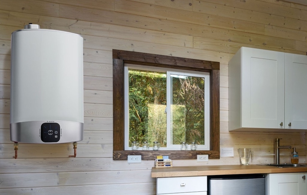
We have underfloor heating in our Spanish apartment, as well as hot-and-cold air-conditioning.
This post is about replacing a defective ‘thermo-electric actuator’ on one of the underfloor heating circuits in our Spanish apartment.
The first surprise is that in many older buildings in the south of Spain, no heating was installed, except possibly an open wood-burning fire. The second surprise is that it can get quite cold in Andalucia in winter, where temperatures can drop to below 10°C between early November and late March. The third surprise is our underfloor heating runs though an electrically-heated water-boiler, and despite electricity prices (€/MWh) being relatively competitive in Spain, it’s still an expensive form of domestic heating.
The positive is that about 20 years ago the architect and builders took the decision to incorporate warm-water underfloor heating in our newly built apartment.
What should underfloor heating look like?
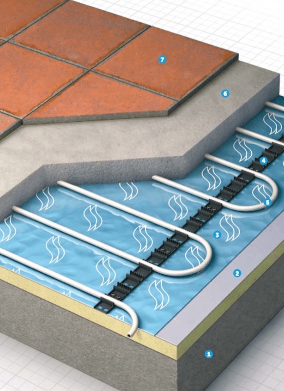
In the above diagram we can see a concrete slab (1), a floor insulation (2), a polythene membrane (3), a clip track (4) to hold the tubing for the hot water (5). Then comes a screed (6), and the floor covering (7).
We can only guess what our actual underfloor heating looks like, but we know what it should look like.
Over the concrete slab floor there should be an insulation layer to stop downward heat loss, and then comes a polythene membrane. On top comes a kind of ‘click pattern’ which holds the underfloor heating pipes in place. Then comes screed which can be hand-mixed or pumped. A less well known fact is that a thick layer of screed can take up to 80 days to properly dry. Then comes the floor covering, which in our case is an antique-style marble.
Who knows if the builder calculated heat loss room-by-room, taking into consideration the floor plan, room volumes, number of external walls, window sizes, losses through the building materials, etc. Did they put in proper insulation, design the best layout for the heating pipes, take into consideration the use of a very dense marble floor covering, etc.?
What do we know about our underfloor heating system?
We received a new-build information pack, but little information on the underfloor heating, and no underfloor heating layout diagrams. Most of the information related to the boiler used for the underfloor heating.
What we do know is that the temperature in each room in the apartment can not be fully controlled, which is poor planning-installation and negatively impacts the overall performance of our heating system. We will come back to this problem later in this post.
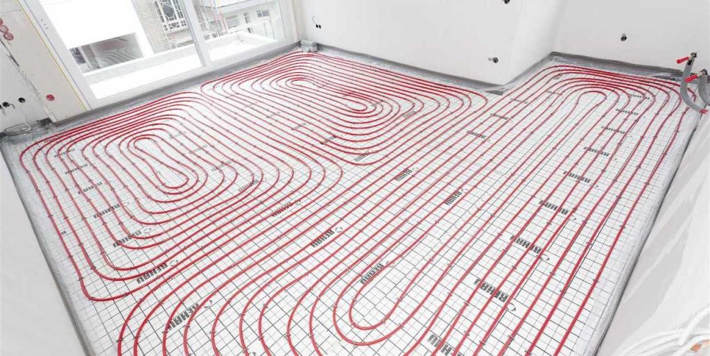
We also know that the laying of heat pipes as seen in this post header would have been impossible. Our pipes are a thick-walled plastic pipe about 2 centimetres in diameter, which could never have been bent and laid as shown above. I’ve no idea if that was standard practice 20 years ago.
One good point about our underfloor heating is that the water boiler appears to normally work at between 35°C and 40°C, but is of course dependent upon the room thermostat settings. This can be considered a low temperature underfloor heating, and is almost certainly better than the alternative with wall radiators running at 45°C or even 55°C.
On the other hand our system takes some considerable to time to heat up and cool down, so the best option is to set a room temperature of 20°C and don’t try to play with it during a day-night cycle. If we need it, we have hot-and-cold air conditioning which is a very fast way to heat up a specific room.
How did I know something was not working?
Simple, the floor in our second bedroom was always warm despite the thermostat in the room being switched off. This meant that the valve on the underfloor circuit in the room was always open.
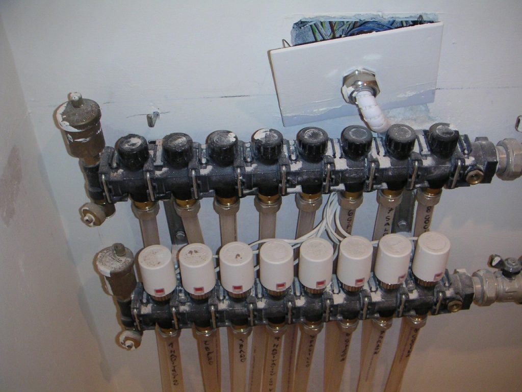
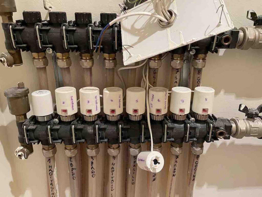
This is not a difficult thing to check. Above we can see the manifold that distributes hot water to the different underfloor circuits. We can see the eight thermo-electric actuators, each sitting on a value head for each hot water circuit. We can see the cable that should be connected to the thermostat placed in each room. We can also see the nice little red marker indicating if the value is open, partially open, or closed. At the back we can also see the manifold for the cooler water returning to the boiler.
Below we can see that the problem was a bit more complicated than initially expected. The thermo-electric actuator fixed to the value controlling the water flowing through the underfloor pipe was broken.
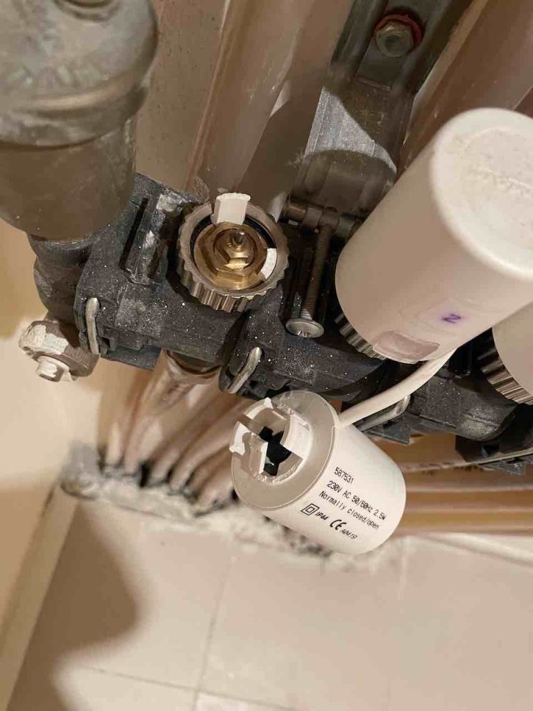
This had almost certainly occurred when the small room housing our floor and domestic water heater was repainted. Some form of stress placed on the actuator had snapped its connection with the value head.
All about thermostatic radiator valves
I guess everyone knows what a Thermostatic Radiator Valve (TRV) is. It’s the device sitting on a wall radiator that controls the room air temperature. It automatically adjusts the amount of hot water entering a radiator.
Most people will have somewhere a centralised boiler system as the primary hot water source. But, they can create different heating zones throughout the house or apartment simply by adjusting the thermostatic radiator valve on each radiator.
A radiator thermostat is a fairly straightforward mechanism, consisting of two main components. They are the valve itself and a thermostat head which screws on to the valve.
The basic design is nearly 100 year old, but as a self-acting mechanism that works with no external energy source, it is still a perfectly good device for controlling a radiator.
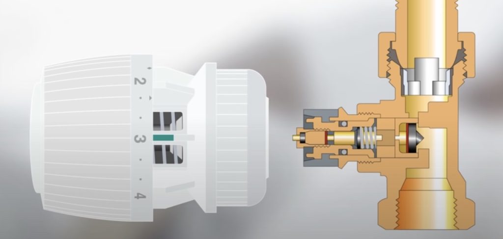
Above we can see the valve, and the pin that opens or closes the flow of hot water to the radiator. The pin is sprung-loaded so in a stationary or null state the value is completely open.
It can happen that as winter approaches, and the value has been closed during the summer, the pin can be stuck closed (and the radiator remains cold). It’s easy to unscrew the thermostat and ‘release’ the pin with a pair of pliers. Normally once released it will again work normally.
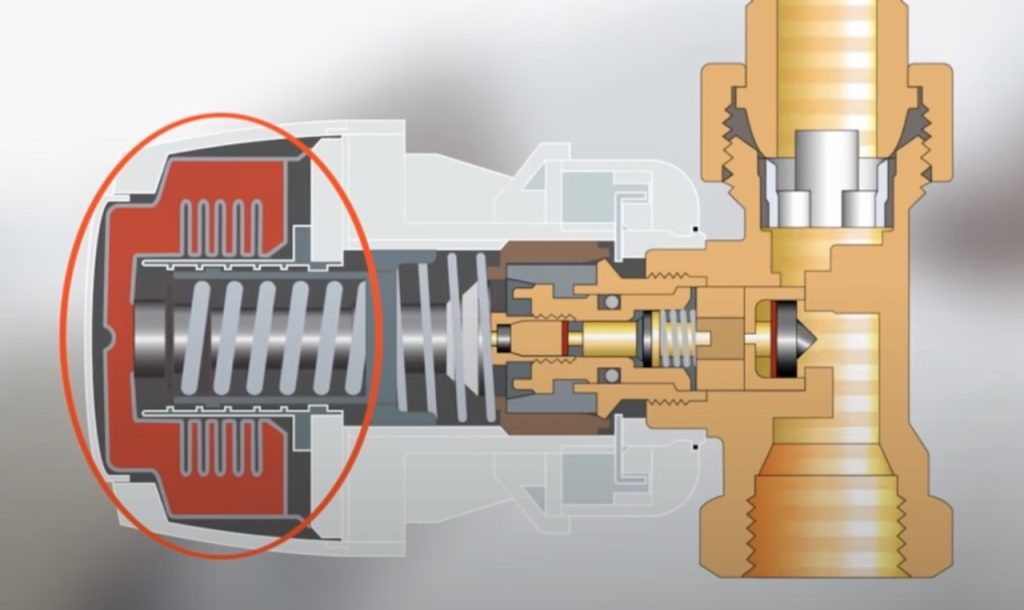
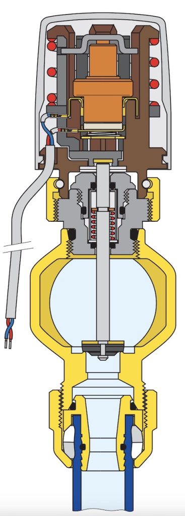
When the temperature in the room begins to change, a capsule in the TRV’s head expands or contracts (as seen above).
It automatically moves a pin in the valve’s body, causing the valve to open or close. If the temperature in the room drops too low the capsule will contract, and the pin will be free to ‘open’, allowing more hot water to flow though the radiator. If the room becomes too warm, the the capsule will expand, and the pin will ‘close’ the valve and reduce the hot water flow.
The capsules in a TRV can adjust the temperature using a metal spring filled with a liquid or a freon based gas, or wax creating what is called a wax motor.
The actuator I used to replace the broken TRV head uses a wax expansion thermostatic element. And I guess the old broken actuator had the same.
More generally there are a number of things that must be considered when looking for a replacement actuator:-
- The most obvious is that the actuator must fit the value head, and the actuator ‘stroke’ (expressed in mm) must correspond to the value being fully closed and fully open. In our installation the ‘stroke’ is 4 mm.
- Secondly, it important to know what was the ‘free state’ of the old actuator. The valve pin when pushed down closes the flow of hot water, but it is important to know if the actuator should be ‘normally open’ or ‘normally closed’. ‘Normally open’ means that when there is no voltage applied to the actuator the value will stay open, and when a volt is applied it will close. The ‘normally closed’ actuator is the reverse, in a voltage free state the valve will be closed. Our actuators are of this second type, when there is no voltage applied, the value is closed. When floor heating is needed, the thermostat closes a circuit, and the value opens.
- Most actuators work on 230 V, but there some that function of 24 V.
- Power consumption should be under 5 W, but lower the better (our new actuator is rated at 3 W).
- It takes between 120 and 180 seconds for the actuator to move from fully closed to fully open, and vice-versa.
- Finally, the old actuator had a red marker showing when the value was open, partially closed, and fully closed. The new actuator did not have a visible indication of the valves position.
Replacing the broken thermo-electric actuator
After 15-20 years it’s often the case that it is impossible to source the exact same component. Fortunately a local ‘fontaneria‘ (plumbers service shop) was able to suggest an alternative.
The old TRV head was from COMAP, but they did not appear to still produce an identical unit to the broken one. I spent hours looking through online catalogues but I could not find what looked like a 100% identical alternative.
My local ‘fontaneria‘ proposed a equivalent unit made by Caleffi, noting that it was not the first time they had proposed this alternative to the original actuator.
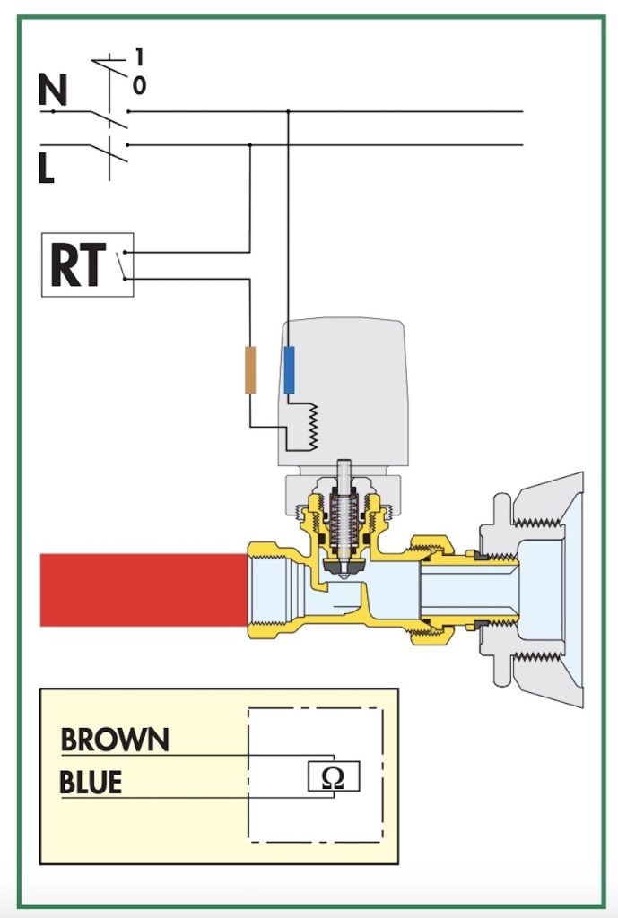
Below we can see the design of the new thermo-electric actuator, and the wiring scheme. Several models of actuator are available, so it was important to take the broken piece to the ‘fontaneria‘ when looking for a replacement.
Did the actuator work first time around?
No.
Following scrupulously the instructions I screwed on the actuator by hand, but it did not work. It was obvious that the joint between the valve head and the base of the actuator had to touch. In the above diagram the brown part had to be touching the grey part.
I had also checked the so-called actuator ‘stroke’ and knew that they were the same in both the old and new actuators. This meant that the opening and closing of the valve should have worked in the same way.
In the instructions there is an explicit statement that the actuator should be hand tighten without using a tool.
My next attempt was to remove some extraneous plastic that appeared to block the proper installation of the actuator (see below).
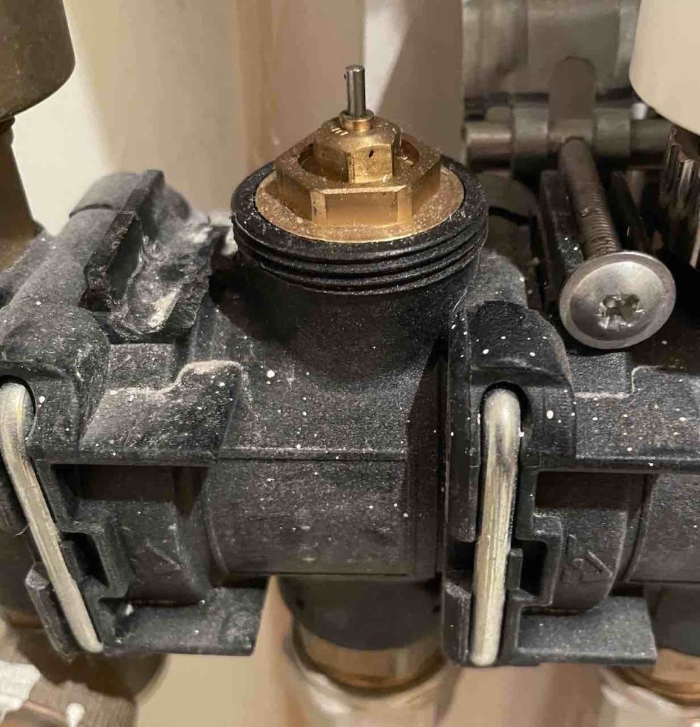
This made it easier to screw on the actuator by hand, but it still did not work.
Next I used a tool to lightly screw down the actuator, but this did not work.
Finally, applying force and ignorance, I tightly screwed down the actuator and it worked. The actuator was physically installed, now it was time to wire it up.
Time to wire it up
It is absolutely vital to isolate the power to the actuators in a local fuse box. And I checked that the electric circuit was dead using a multimeter.
It was not difficult to isolate the cable of the old actuator, and cable in the new actuator. And it worked.
The cabling - what an unprofessional mess
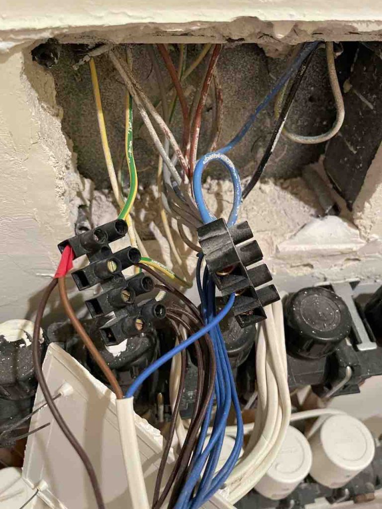
The cabling of the actuators was a totally unprofessional mess.
However, the key point was that not only was it a mess, but it also did not cable properly the eight actuators in place.
We can see eight actuators, but in the apartment we only have four thermostats, in the living room, main bedroom, main bathroom, and second bedroom.
Yet we have underfloor heating throughout the apartment, including in the kitchen, second bathroom, and hall.
What the original installer did was to join the second bedroom and bathroom together, which might be considered a sensible option if used as an occasional guest bedroom (which it is).
We have two circuits in the living room which are connected together, and connected with the hall and the kitchen. I would have much preferred a separate temperature sensor in the kitchen, and I would even have accepted no heating in the interior hall.
I would note that it is perfectly possible to control multiple zones with actuators in parallel using the same thermostat, however it is usually recommended to insert an intermediate relay to prevent electrical overload, and this was not done.